1. AND Gate
Logic Diagram :
 |
| AND Gate |
- The AND gate is an electronic circuit that gives a high output (1) only if all its inputs are high.
- A dot (.) is used to show the AND operation.
AND Gate Truth Table :
|
Inputs |
Output |
|
|
A |
B |
|
|
0 |
0 |
0 |
|
0 |
1 |
0 |
|
1 |
0 |
0 |
|
1 |
1 |
1 |
2. OR Gate
Logic Diagram :
 |
| OR Gate |
- The OR gate is an electronic circuit that gives a high output (1) if one or more of its inputs are high.
- A plus (+) is used to show the OR operation.
OR Gate Truth Table :
|
Inputs |
Output |
|
|
A |
B |
|
|
0 |
0 |
0 |
|
0 |
1 |
1 |
|
1 |
0 |
1 |
|
1 |
1 |
1 |
3. NOT Gate
Logic Diagram :
 |
| NOT Gate |
- The NOT gate is an electronic circuit that produces an inverted version of the input at its output.
- It is also known as an inverter gate.
NOT Gate Truth Table :
|
Inputs |
Output |
|
A |
|
|
0 |
1 |
|
1 |
0 |
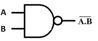
4. NAND Gate
Logic Diagram :
 |
| NAND Gate |
- This is a NOT-AND gate which is equal to an AND gate followed by a NOT gate.
- The outputs of all NAND gates are high if any of the inputs are low.
- The symbol is an AND gate with a small circle on the output.
- The small circle represents inversion.
NAND Gate Truth Table :
|
Inputs |
Output |
|
|
A |
B |
|
|
0 |
0 |
1 |
|
0 |
1 |
1 |
|
1 |
0 |
1 |
|
1 |
1 |
0 |
5. NOR Gate
Logic Diagram :
 |
| NOR Gate |
- This is a NOT-OR gate which is equal to an OR gate followed by a NOT gate.
- The outputs of all NOR gates are low if any of the inputs are high.
- The symbol is an OR gate with a small circle on the output.
- The small circle represents inversion.
NOR Gate Truth Table :
|
Inputs |
Output |
|
|
A |
B |
|
|
0 |
0 |
1 |
|
0 |
1 |
0 |
|
1 |
0 |
0 |
|
1 |
1 |
0 |
6. EXCLUSIVE-OR Gate
Logic Diagram :
 |
| Exclusive-OR Gate |
- The 'Exclusive-OR' gate is a circuit which will give a high output if either, but not both, of its two inputs are high.
- An encircled plus sign (
) is used to show the Exclusive-OR operation.
Exclusive-OR Gate Truth Table :
|
Inputs |
Output |
|
|
A |
B |
|
|
0 |
0 |
0 |
|
0 |
1 |
1 |
|
1 |
0 |
1 |
|
1 |
1 |
0 |
7. EXCLUSIVE-NOR Gate
Logic Diagram :
 |
| Exclusive-NOR Gate |
- The 'Exclusive-NOR' gate circuit does the opposite to the Exclusive-OR gate.
- It will give a low output if either, but not both, of its two inputs are high.
- The symbol is an Exclusive-OR gate with a small circle on the output.
- The small circle represents inversion.
Exclusive-NOR Gate Truth Table :
|
Inputs |
Output |
|
|
A |
B |
|
|
0 |
0 |
1 |
|
0 |
1 |
0 |
|
1 |
0 |
0 |
|
1 |
1 |
1 |